Why Every WLED Controller Ships Blind (And What It Takes to Fix That)
Per-channel current monitoring on a WLED controller is harder than it looks. INA219 address limits, shunt sizing, dual power rails, and level shifting — solved.
A standard WLED controller writes PWM values to a bank of MOSFETs and hopes for the best. It has no idea how much current any channel is pulling. Short a strip, overload a channel, push a connector into thermal runaway, and the firmware never knows. It keeps writing duty cycles into the dark.
That is fine for a breadboard. It is not fine for a product you ship to someone’s house. The first post in this series, “Finding the Gap,” covered why per-channel current sensing is the missing feature in the WLED ecosystem. This post covers why adding it is harder than dropping four sense chips on a board, and what the v1.0 board settles.
The Controller Is Blind By Design
The typical ESP32 WLED build has one job on the output side: take a color and brightness, convert it to PWM, drive the gate of a MOSFET per channel. Data flows one direction. There is no return path that tells the ESP32 what actually happened on the LED rail.
So the failure modes are all invisible. A pinched strip that shorts to frame ground pulls hundreds of milliamps through a trace rated for less. A daisy chain that grew past its power budget browns out at the far end. A connector with a cold joint heats up under load. The controller sees none of it because it was never wired to look.
Closing that loop means measuring current on every channel and getting that data back to the ESP32 fast enough to act on it. That is where the hard part starts.
The INA219 Address Space Runs Out Fast
The INA219 is the obvious part for the job. It is an I2C current and power monitor: it reads voltage across a shunt, does the math, and hands you current and power over the bus. Cheap, well documented, supported everywhere.
It has two address pins, A0 and A1. Each can tie to GND, VS+, SDA, or SCL, which gives 16 addresses from 0x40 to 0x4F. In theory that is plenty.
In practice most layouts only route the GND and VS+ options on the address pins. That collapses 16 addresses down to 4. A four-channel controller needs one INA219 per channel. Four channels, four addresses. You are exactly at the wall.
Add a fifth channel and the cheap path is gone. Now you choose:
- Switch to the INA3221, which monitors three channels per chip and has two device addresses, giving six channels on one bus.
- Add a second I2C bus so you can reuse the same four addresses again.
Neither is free. The INA3221 has a lower full-scale shunt range and a shared common ground that complicates layout. A second bus costs you two more GPIO and more routing. The point is that “just add another channel” quietly turns into an architecture decision. Four channels is the sweet spot where one bus and four default addresses line up cleanly, which is why v1.0 lands there.
Two Voltage Domains, One Bus
A WLED board runs two power domains. The LED strips want 5V or 12V at high current. The ESP32 wants 3.3V and clean I2C. Current monitoring has to live on the high-current LED side, but the bus it reports on belongs to the 3.3V side. Those two facts fight each other.
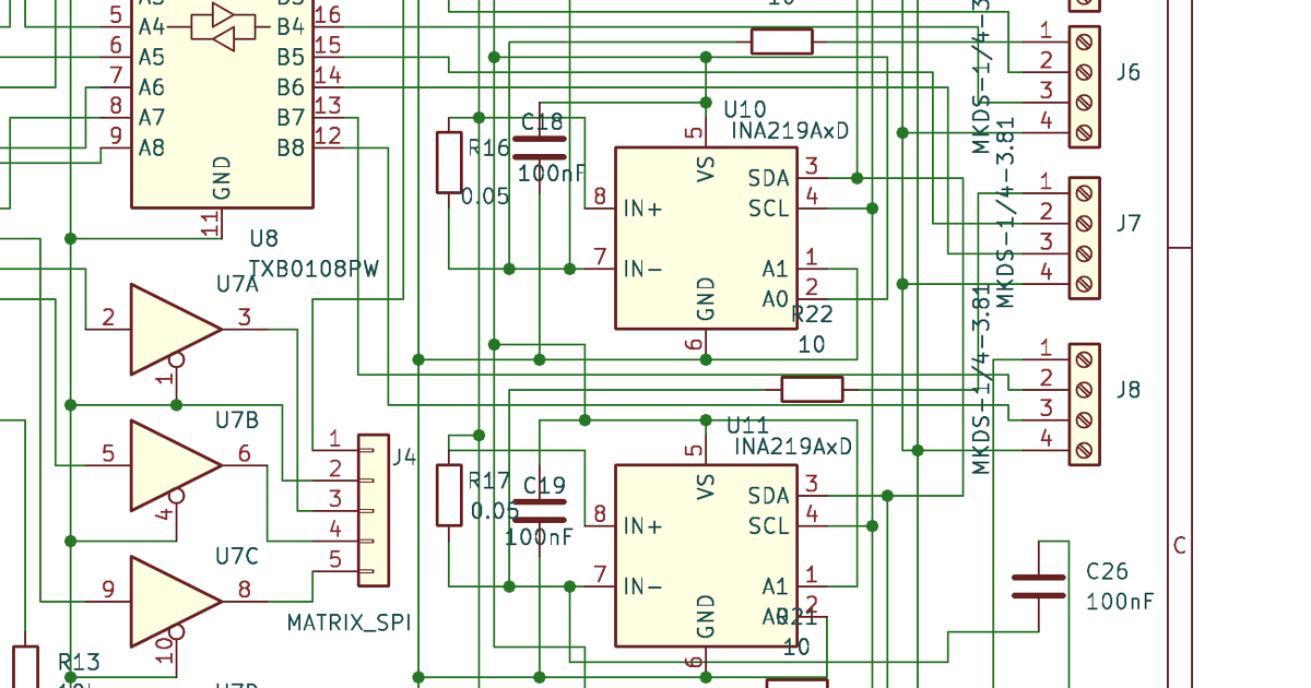
The INA219 helps here. Its IN+ and IN- inputs tolerate common-mode voltage up to 26V, so the shunt can sit on the 5V (or 12V) rail with no trouble. But the chip’s VCC and I2C pins are a separate question, and how you power them decides what else you have to build.
Power the INA219 from 3.3V and its I2C lines already match the ESP32. The shunt still sits on the LED rail, and as long as your supply voltage stays inside the 26V common-mode window, the measurement is fine. No level shifting needed. This is the clean path, and it is the one v1.0 takes.
Power the INA219 from 5V and its I2C outputs now swing to 5V. Which brings us to the pin-killer.
5V I2C Into a 3.3V ESP32 Kills Pins
ESP32 GPIO is not 5V tolerant. Run a 5V I2C line into it and you will damage the pin. Sometimes it dies on the first power-up. Sometimes it limps through a few power cycles and then fails in the field, which is worse, because now it is a return instead of a bench mistake.
If any part on the bus is VCC’d from 5V, you need bidirectional level shifting on both SDA and SCL. Two real options:
- A BSS138-based discrete shifter. Cheap, proven, the standard reference circuit. Costs you component count and a bit of layout care per line.
- A dedicated part like the TCA9406. Cleaner schematic, fewer placement headaches, but another BOM line.
This is not a “nice to have.” It is the difference between a board that works and a board that bricks its own GPIO. The way to avoid the whole problem is to keep the INA219 on the 3.3V rail in the first place, which is exactly why that choice cascades through the rest of the design.
Shunt Sizing Bites You At Both Ends
The INA219 does not measure current directly. It measures voltage across a shunt resistor and you back out the current. Pick the shunt wrong and you lose either efficiency or resolution.
Go too high. A 5A channel through a 100mΩ shunt drops 500mV and burns 2.5W in a single resistor. That is wasted power, real heat, and a meaningful voltage sag at the strip. Unacceptable on a high-current channel.
Go too low. The INA219 full-scale range is ±320mV. At 10mΩ and 1A you only develop 10mV across the shunt. Noise starts eating your low-end resolution, and your current readings get mushy exactly where you might want fine detail.
For a 5V, 5A-per-channel system, 10mΩ is the honest compromise:
- 50mV drop at full 5A load
- 250mW dissipated in the shunt
- Usable resolution across the working range
The catch is that 10mΩ is small enough that copper matters. A few milliohms of trace resistance in the measurement path is a sizable fraction of 10mΩ, and it shows up as a direct error in your reading. So you cannot use a generic 0805 and call it done. You want a precision low-inductance shunt, and you want a four-terminal (Kelvin) connection so the sense lines tap the resistor element itself, not the high-current copper feeding it.
What v1.0 Resolves
The v1.0 board commits to a set of answers instead of leaving them open.
- Four channels. One I2C bus, four default INA219 addresses, no address juggling and no second bus.
- One INA219 per channel, all on the 3.3V rail. I2C matches the ESP32 natively, so there is no level shifting in the signal path and no 5V threat to the GPIO.
- Shunts on the LED power path, inside the 26V common-mode window. Measurement happens where the current actually flows.
- 10mΩ four-terminal Kelvin shunts. Trace resistance drops out of the measurement, so the readings reflect strip current, not board copper.
- BSS138 level shifters available on both I2C lines where the design needs the headroom, using the proven reference circuit.
With that in place, the ESP32 finally has real-time per-channel current data, exposed to WLED through a custom driver. Overcurrent detection becomes possible. So does thermal protection logic and per-channel energy accounting. The controller can react to a shorted strip instead of cooking it.
The controller is no longer blind.
Conclusion
None of these problems are exotic on their own. Address allocation, voltage domains, shunt math, level shifting: each is a solved problem in isolation. The work is in making the four choices agree with each other, because the cheap answer to one constraint is often the expensive answer to the next. Keeping the INA219 on 3.3V kills the level-shifting problem. Choosing four channels keeps the address space clean. Picking 10mΩ forces the Kelvin shunt. The design only holds together as a set.
That is the gap between a hobbyist prototype and a board you can ship, and it is the gap this Kickstarter is built to close. If you build LED installations, run WLED at any real scale, or just want a controller that can see what it is doing, follow the series. The next post gets into the firmware side: getting that current data into WLED and acting on it in real time.
Have a use case or a horror story about a strip that browned out or a controller that fried a pin? I want to hear it. Reach out — it shapes what goes on the board.